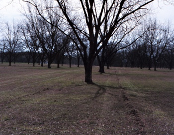
pecan tree irrigation piping outline drawing
- Advantages of Drip Irrigation
- Disadvantages of Drip Irrigation
- Components of Drip Irrigation Systems
- Design and Installation of System Components
- Filters
- Energy for Irrigation
- Water Sources for Irrigation Systems
- Agricultural Water Use Permits
- Equations for Pump Requirements
- Operational Requirements
- Maintenance
- Summary
Research conducted on drip-irrigated pecans in Georgia over the past several years has shown that drip irrigation is highly beneficial even in wet years. This has been confirmed by growers who use it and by the number of systems being installed each year.
Drip irrigation is the frequent, slow application of water to the soil through mechanical devices or holes called emitters (drippers or applicators) located along the water delivery line. This eliminates spraying or running water down furrows and supplies filtered water under low pressure directly onto or into the soil. Water is carried through a pipe network to each plant. Emitters dissipate the pressure in the pipe distribution network by means of either a small-diameter orifice or long flow path, thereby decreasing the water pressure to allow discharge at low volumes of water per hour. After leaving the emitter, the water is distributed by its normal movement through the soil profile. Therefore, the area that can be wetted from each emitter is limited by the water's horizontal movement in the soil.
The objective of drip irrigation is to supply each plant with sufficient soil moisture to meet transpiration demands. Drip irrigation offers unique agronomic, agrotechnical and economic advantages for the efficient use of water.
Advantages of Drip Irrigation
The main advantages of drip irrigation are:
- It allows maximum beneficial use of available water supplies by controlling water flow to allow maximum crop yields with the greatest economy in water use.
- Evaporation losses are minimized since water is discharged at or below ground level.
- Pressure requirements are low resulting in lower operating costs.
- Labor requirements are usually lower than with most other types of irrigation.
- Irrigation can be applied during mechanical operations.
- Fertilizers and other chemicals can be applied through the system.
- Plant protection from diseases and insects is improved by not wetting plant leaves.
- Reducing the wetted area limits weed growth and restricts populations of potential pest hosts.
- Effect of wind on the wetting pattern is nil, which allows round-the-clock irrigation with lower flow rates and a resultant reduction in pipe sizes and easier adaption to existing water supplies.
- Most systems display the well-known advantages of permanency.
- Systems are readily adapted to automatic controls.
- Drip irrigation provides improved infiltration in soils with low intake capacity.
- It allows satisfactory use of more saline water.
Disadvantages of Drip Irrigation
Although drip irrigation offers several advantages for the grower, the system has disadvantages, problems and limitations.
- The water supply must be free of soil particles to function properly. An adequate and dependable filtering system is difficult to provide.
- Emitter clogging can result from poor water filtration, algae, bacteria, sulfur, iron and calcium in the water. Non-uniformity of water discharged from the emitters causes additional complications.
- On sandy soils, drip irrigation does not provide adequate water distribution. The water does not tend to move laterally; therefore, insufficient root volume is wetted causing high water use and leaching of nutrients.
- Mice and other animals sometimes chew on the flexible plastic pipes, causing considerable damage.
Components of Drip Irrigation Systems
A drip irrigation system consists of emitters, lateral lines, main lines, filters, control valves and, as in all systems, a pumping plant and water source. The pumping plant and water source are usually the most expensive items. The purpose of this publication, however, is to answer the questions asked most frequently by growers, not justify the economics.
Emitters
The emitter controls the flow from the lateral line into the soil. Emitters range from simple porous wall pipe (line source) to complicated mechanical passageway (point source) units (Figure 1). The emitter decreases the pressure (reduces the head) from the lateral line to the soil. This may be done by small holes, long passageways, vortex chambers or other mechanical means. The pressure of some emitters may be regulated by changing length of cross section of passageways, size of orifice or flow patterns.
Emitters can be placed on the soil surface (Figure 2), or they may be buried at shallow depths for protection. Rates of flow from point source emitters are usually fixed from 1/2 gallon per hour up to 60 gph (microsprinklers). However, rates on some emitters can be manually adjusted. Emitters used in pecan orchards typically have an output rate of 2 gallons per hour. The emitters are connected to or are a part of the lateral line and can be either self-cleaning or manually cleaned.
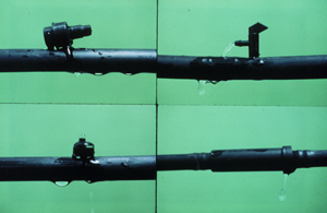 Figure 1. Typical emitters for drip irrigation of pecans. Counterclockwise from upper left: Pressure compensating self-flushing emitter; Pressure compensating emitter; Mechanical passageway, in-line, non-flushing emitter; Mechanical passageway manual cleaning emitter.
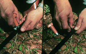 Figure 2. Installing an emitter on an above-ground lateral line.
Lateral Lines
The lateral lines are small in diameter (3/8 to 3/4 inch), and placed one or two per tree row (Figure 3). Whether you use one line or two depends on the cost and system design. Some systems must have two lines per tree row to achieve adequate distribution of water around the tree. The lines are manufactured from polyethylene (PE) material not black polyvinylchloride (PVC). The PE material is more resistant to sunlight than the black PVC. The PE material is also used because of its high strength and impact resistance properties. The lines can be installed on the ground surface or buried below ground surface depending on system design and owner preference. Buried systems are usually installed 4 to 6 inches below ground surface.
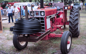 Figure 3a. Lateral line used in drip irrigation.
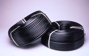 Figure 3b. Lateral line used in drip irrigation.
Main Lines
The main lines carry water to the lateral lines from the pump. They are made of plastic and are buried (Figure 4). Their size depends on the required water flow to the laterals. In most cases, the sizing of the main line is the most difficult task. Pressure (friction) losses must be kept to a minimum if uniform distribution of water is to occur.
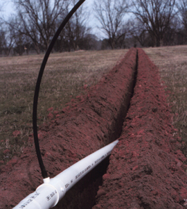 Figure 4a. Installing PVC mainline.
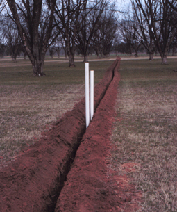 Figure 4b. Installing PVC mainline.
Control Valves
Mechanical pressure regulators (made of either brass or plastic) may be required to maintain the system near the design pressure. Pressure required for different emitters ranges from 2 or 3 psi (pounds per square inch) to 30 or 40 psi. Other control valves that may be required include on-off valves to control the flow of water from one zone to another zone and valves to "flush" the ends of PVC lines where sediment may collect. Figures 5-8 illustrate the various types of control stations that may be encountered in the field.
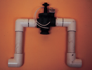 Figure 5a. Control station consisting of one solenoid valve for automatic on-off control.
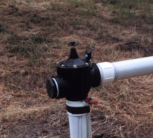 Figure 5b. Control station consisting of one solenoid valve for automatic on-off control.
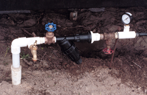 Figure 6. Control station with (from left) manual on-off valve, filter, pressure regulator, secondary manual on/off valve and pressure gauge.
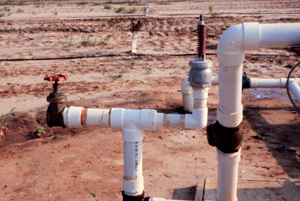 Figure 7. Control station with flush valve (left) and pressure relief valve (right).
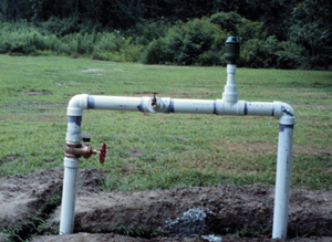 Figure 8. Control station with manual on-off valve (left valve), injection port (center valve) and kinetic air relief valve (right valve).
Filters and Screens
Most water must be cleaner than drinking water to be used in drip irrigation. To ensure clean water, various types of sand or cartridge filters and screens of 80 to 200 mesh are used, individually or in combination. The sand filter can have manual or automatic backflushing devices for cleaning. The cartridge filter is changed when dirty, and screens are normally cleaned by hand. Figure 9 shows the simple screen filter installation.
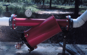 Figure 9a. Simple screen filter installation.
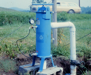 Figure 9b. Simple screen filter installation.
Design and Installation of System Components
A primary objective of good drip irrigation system design and management is to provide sufficient system flow capacity to adequately irrigate the least-watered tree without overwatering any trees. Uniformity of application depends on the uniformity of emitter discharge. Nonuniform discharge is caused by clogging, pressure differences in the system and manufacturing tolerances.
Emitters
The appropriate emitters to use will depend on topography and the crop to be irrigated. If the topography is uneven, extra precautions will need to be taken in the design. The emitter may need to be a pressure-regulating type emitter; the system may have to be designed so the lateral lines are on the contour, or the operating pressure will have to be high enough so the differential pressures (pressure differences between emitters) will be small or negligible. In orchards, the tree spacing, the number of emitters per tree (wetted area under the tree) and emitter discharge will determine the amount of water delivered per tree and the flow necessary in the lateral line.
Research indicates that the minimum water requirement for pecans in Georgia is 2,400 gallons per acre per day. This amount of water will keep plants alive but may not be adequate for significant yields. It can be as high as 5,000 gallons per acre per day for some orchards to maintain significantly high yields. As the plants per acre increase (spacing gets closer) the amount of water to use per day generally increases. You may need to adjust this rate to fit your situation and equipment limitations. Use the following equation to help you determine certain parameters for your orchard:
E = V/(NxFxH)
Where:
E = the number of emitters installed per tree
V = volume of water applied in gallons per acre per day
N = number of trees per acre
F = emitter flow rate in gallons per hour
H = hours per day that the system will be operated
For a given orchard, the number of trees per acre (N) is fixed. The output of the emitters (F) is most commonly 2 gph but can be other values. The volume of water applied per day (V) will vary during the year but should be high enough to satisfy your needs. For this example it will be 3,600 gallons per acre per day. Therefore, for a given orchard, only two values (E and H) must be determined.
Example:
Use pecans spaced 60 feet x 60 feet and a 2 gph emitter. For this situation N = 12.1 trees/acre, and V = 3600 gal./acre/day, therefore,
E = 3600/(12.1 x 2 x H)
By inserting values for H and solving for E, the following table can be developed:
| Option # | E — emitters per tree | H — hrs of operation/day |
| 1 | 8 | 18.6 |
| 2 | 10 | 14.9 |
| 3 | 12 | 12.4 |
| 4 | 14 | 10.6 |
| 5 | 16 | 9.3 |
Drip irrigation systems should not operate more than 15 hours per day on any one zone. Watering longer than this could saturate the soil profile and deplete available soil air to the roots. The preferred operation time is 12 hours or less per zone per day. Also, the total wetted area (number of emitters) under the tree should be adequate to wet the majority of the root system. Therefore, options 2, 3, 4 and 5 above are acceptable for this example.
If the system is designed to operate in halves, then it must operate no more than 12 hours per zone per 24 hours (i.e., half of total operating time per zone). The condition of no more than 12 hours operation time rules out option 2 and leaves option 3 as a marginal choice. This leaves options 4 and 5 as acceptable. The decision of which option to select depends on the initial cost of the system. Obviously, the more emitters you install per tree the more expensive the system will be. Also, the more emitters you install the larger the pump and well have to be, adding to the initial cost. The most economical option is option 4. With this option each zone will be watered about 12 hours per day to receive slightly less than maximum design water. For a system operating in halves, this is a total operating time of 24 hours per day. This situation does not allow for any downtime and maintenance during peak water needs but does allow for some catch-up capacity during other time of the year.
Placing the emitters around the tree becomes the next concern. You can place the emitters along one side of the tree or both sides of the tree. Factors affecting this decision are adequate water distribution, economics and system design. A compromise will usually have to be made. That is, the least expensive system (installed on one side) may not yield adequate water distribution and have unacceptable design parameters, while a system designed for precise water application per tree will be the most expensive. You may have to install emitters on both sides of the tree to satisfy the water distribution demands and maintain acceptable design parameters. Generally, if the tree spacing is narrow (fewer than 50 feet) one emitter line is adequate; for wider spacings, two emitter lines per tree row are usually desirable.
Some emitters are manufactured as an integral part of the tubing and are factory-installed at specific intervals. These are called in-line emitters. It is better to install this type emitter entirely above ground.
The other type of emitter is inserted into the tubing at the desired locations by the installer. These are called point-source emitters. They may also be installed above ground (Figure 10), but more often they are installed 4 to 6 inches below the surface (Figure 11). If emitters are installed underground, the water should be ported to the surface using small diameter tubing that extends from the emitter to 1 or 2 inches above the ground surface (Figure 12). This allows the operator to visually check the system operation and to periodically determine the emitter output rate. Porting also helps prevent the emitters from being clogged by dirt.
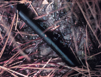 Figure 10a. Above ground installation of emitter and lateral line.
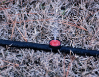 Figure 10b. Above ground installation of emitter and lateral line.
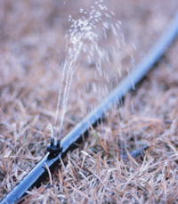 Figure 10c. Above ground installation of emitter and lateral line.
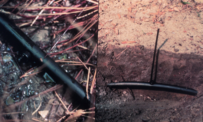 Figure 11. Above ground installation (left) and same emitter installed below ground with emitter "ported" to surface (right).
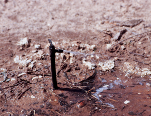 Figure 12. Below ground installation of lateral line and above ground installation of emitter.
A special type of emitter sometimes used in drip irrigation is called a Microjet® (Figure 13). These emitters spray water over a larger area than that normally wet by emitters mentioned previously. They are especially useful in sandy soil types where lateral movement of water is limited. The Microjet® spreads the water over the area then it is allowed to penetrate the soil profile. The two main disadvantages of the Microjet® are 1) it is an above ground obstacle subject to damage from mechanical harvesting equipment and, 2) evaporative losses have to be accounted for just as in sprinkler irrigation. The design and installation of components for a Microjet® system are identical to those used with other drip emitters.
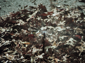 Figure 13a. Microjet® installation.
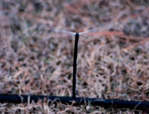 Figure 13b. Microjet® installation.
Lateral Lines
The most frequently asked questions about lateral lines are "How far from the tree should they be buried?" and "How long can they be?" How far you can run the lateral line from the main line depends more on design than anything else. It is true that, for the same conditions (emitters per tree, slope, etc.), two lines can be run farther than one line. In most cases one line can be run up to 300 feet and two lines run up to 600 feet. Use these numbers as a guide. They are not considered the "rule" in design because other factors must be considered. Have a competent irrigation designer evaluate the maximum length of lateral lines.
Use a common-sense approach when deciding how far away from the tree to install the lateral line. How close to the tree the line is installed depends on the equipment used and the age of the tree. You do not want to get too close and damage essential brace roots on mature trees. The equipment used to install the tubing is usually mounted on the rear of a tractor; however, it is sometimes mounted on the front and rear (Figure 14). The wheel spacing on the tractor will, therefore, limit how close you can get. Should the trees be young trees, which means that brace roots are of no concern, you should still consider where the feeder roots will be in years to come. For these reasons, the lateral lines are usually installed no closer to the tree than 4 feet.
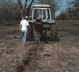 Figure 14a. Installing lateral line using subsoil plow — rear mounted equipment.
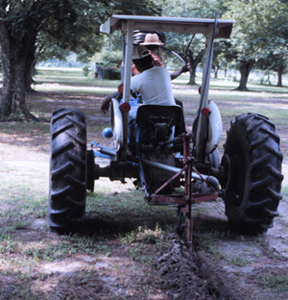 Figure 14b. Installing lateral line using subsoil plow — both front and rear mounted equipment.
How far away the tubing is installed from the tree depends on management practices. Most orchards have a herbicide strip, and the lateral lines are placed in the outer edge of this strip. The farther the lateral lines are from the tree, the wider the herbicide strip must be. You could be spraying as much as two-thirds of your orchard floor with herbicide, which can be very expensive. Also, at some distance from the tree you reach a point where lateral lines are usually installed no more than 10 feet from the tree. In most orchards the distance of the lateral lines from the tree row will be 6 to 8 feet (Figures 14 and 15).
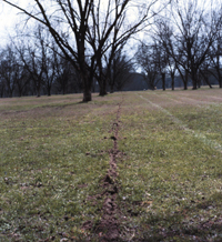 Figure 15a. Finished installation of lateral lines.
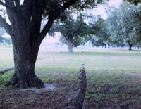 Figure 15b. Finished installation of lateral lines.
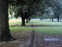 Figure 15c. Finished installation of lateral lines.
Mainlines
Mainlines are usually rigid PVC pipe. In a small system only one size pipe or pressure-rated pipe may be used, while in larger systems several sizes and pressure ratings of pipe may be used. Because of its rigid construction, the pipe must be installed deep enough to withstand heavy surface loads such as sprayers. It must also be below the "frost-line" so the stress of freezing and thawing water will not burst the pipe. The frost-line in Georgia is shallower than the depth required for withstanding heavy surface loads.
The minimum required depth of cover for PVC pipelines is as follows:
| Pipe Size (in.) | Minimum Depth of Cover (in.) |
| 1/2 - 2 1/2 | 18 |
| 3-4 | 24 |
| 4 or more | 30 |
Several methods exist for connecting the mainline to the lateral lines. Since the mainline is usually deeper than the lateral line, either the mainline must be brought up to the lateral line or the lateral line taken down to the mainline. It is usually more economical and easier to take the lateral line down to the mainline (Figure 16).
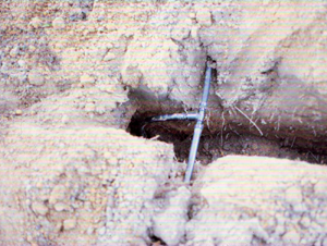 Figure 16. Connecting lateral line to PVC.
Filters
Filters commonly used in drip irrigation are screen or sand filters, and their size is determined by the amount of water flowing through them. Vortex (or other) sand separators and settling ponds are used to remove heavy loads of sand.
Screen Filter
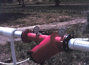 Figure 17. Simple screen filter installation.
Screens, which are the simplest method of cleaning water, efficiently remove very find sand from the irrigation water (Figure 17), but tend to be clogged rapidly by heavy loads of algae and other organic material. Clean them whenever the pressure drops (more than 7-10 PSI) across them. The most common methods of cleaning are 1) manual cleaning — pulling out the screen and cleaning it by washing, 2) cleaning by repeated washing (blowing-off) of the screen without dismantling, and 3) automatic cleaning — either continuously, on a time schedule, or whenever the pressure loss across the screen reaches a certain level.
Regardless of the cleaning method you use, take extreme caution to prevent dirt from by-passing the screen during cleaning. Backflushing with pre-cleaned water is recommended. Also, downstream safety screens such as hose washer screens at each lateral connection provide an additional safeguard. Secondary filters are especially important in case of accidents, such as main line breaks. A few handfuls of sand or organic particles large enough to clog the emitters could severely damage your system.
Sand (Media) Filters
Media or sand filters consist of fine gravel and sand particles of selected sizes placed inside a cylindrical tank (Figure 18). Media filters remove heavy loads of very fine sands and organic material and are often constructed so they can be automatically backwashed as needed. Media filters are almost always recommended when surface water, such as from a pond or stream, is used for drip irrigation. A recommended practice is to place a screen downstream from the media filter to pick up any particles that might escape during backwashing.
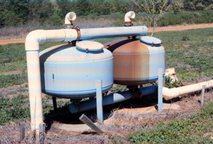 Figure 18a. Sand (media) filter installation.
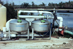 Figure 18b. Sand (media) filter installation.
Vortex Sand Separators
Modern vortex (centrifugal) sand separators can remove up to 98 percent of the sand particles that would be retained by a 200-mesh screen. They depend on centrifugal force to remove and eject high-density particles from the water and, consequently, cannot remove organic materials. Although vortex separators do not remove all the required particles, they are an efficient device for ejecting large quantities of very fine sand before further screening (Figure 19).
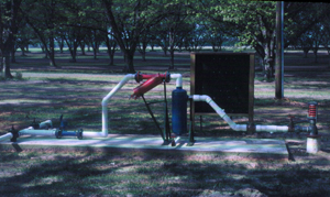 Figure 19a. Screen filter and vortex sand separator installations.
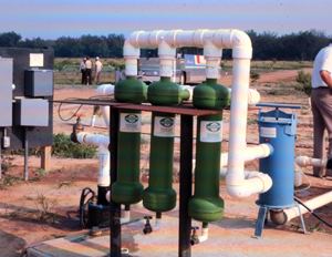 Figure 19b. Screen filter and vortex sand separator installations.
Energy for Irrigation
Individuals should use the most economical and readily available source of energy. Many electric suppliers are offering electricity for irrigation purposes at a special rate. Other charges such as line extension (construction) charges and monthly minimum (standby) charges may apply and must be investigated before you make a decision.
Discuss this with the electric supplier you will use, because charges will vary from one supplier to another. If you use electricity, you may have to change the design of the irrigation system because the electrical supplier may turn off the power during peak electrical demand periods. You should, therefore, contact the electrical supplier before you sign the contract for the irrigation system.
Water Sources for Irrigation Systems
The two types of water sources used for irrigation in Georgia are surface water supply and groundwater supply. Remember, water is needed most when the supply is at its lowest level, so water sources should be adequate to supply water during extended dry periods.
Surface Water
Surface water is available from two primary sources; ponds and streams (rivers). A small number of the irrigation systems in Georgia are using streams or rivers. The obvious reason for this is because major tributaries suitable for supplying an irrigation system are not located near most farmland. For those systems that can use stream flow, the doctrine of riparian rights governs the use of the stream water.
The doctrine of riparian rights states that an owner of property adjacent to a stream can make reasonable use of that stream, but may not appreciably diminish the flow of the stream. This is not compatible with irrigation needs because many times the irrigator will use almost the total stream flow either by constructing a low dam across the stream or diverting the stream into a reservoir. Before pumping or installing the irrigation system on a stream, contact local authorities to ensure that no regulations are being broken. In some areas, streams may be a portion of a city water supply system and irrigation pumping may not be allowed. Also, in some areas, local ordinances have restricted the construction of dams across streams.
A pond can be constructed in any location that has soil suitable for the construction of a dam and a watershed large enough to support the irrigation system. Base the size of the pond on the acres to be irrigated. For most areas of Georgia, the general rule is 1 acre-foot of water storage for each acre of land to be irrigated. Thus a 10-acre pond with an average depth of 10 feet would be needed to irrigate 100 acres. This rule assumes no recharge to the pond from ground water or underground springs. If you have a spring-fed pond, adjust the storage capacity of your pond accordingly.
Several guidelines are available on the construction of a pond, and the cost of construction will vary depending on which guideline is used. Be sure to check with the appropriate local authorities before construction. A pond or dam located at one site might not require any special permits for construction, while the same size pond or dam at another site will require special permits for construction.
Using surface waters for drip irrigation usually means using sand (media) filters. This is necessary to ensure that clean water is delivered to the system. The cost of the filter in some cases is more than a well would be for the same job requirements, therefore, costs will be a determining factor. Therefore, keep filtration costs in mind when considering which water source (ground water or surface water) to use.
Ground Water
The use of wells in Georgia continues to increase. Depending on the location within the state, well type and size, capacities up to 3,000 gallons per minute are possible. In the southern half of Georgia groundwater is generally available in larger quantities. In North Georgia sufficient quantities of groundwater may or may not be available depending on location.
Several types of irrigation wells can be constructed. One type is the open end well. Normally, this is a single-pipe construction, but it may have two pipes. This type of well is typically used in limestone formations.
The second type of irrigation well is the tubular type sand well. It is the least expensive well in a sand formation. This well must be cased the entire length to prevent sand infiltration. With non-homogenous sand, a screen with a slot size of 0.010 to 0.060 inches will suffice for this type of well. In nonhomogeneous sand, the finer particles are pulled through the screen; the coarser particles remain outside and build up a natural filter, which prevents the rest of the sand from entering the well. With uniform sand, a gravel pack or developed well must be used. The difference between the tubular type sand well and the gravel pack well is that a filter bed is formed with gravel in the latter. With this type well, a hole is drilled that is normally twice the diameter of the well casing. A well casing is placed, along with appropriate screens, and then gravel or sand of a variety of sizes is placed around the screen to form a natural filter that will allow water, but not sand, to enter. The gravel packed well is the most expensive per gallon of capacity. For most irrigation wells, it is recommended that a test well be drilled prior to drilling the larger well. This will give the driller a much better idea of potential capacity, water bearing strata, depth and actual cost of construction.
There are two ways to purchase a well. One is a lump sum contract that guarantees a certain quantity of water for a fixed cost. The driller takes all the risk. The other method — unit price method — is the least expensive since the purchaser pays for only the work that is done. The purchaser gets only what he needs, but he must have confidence in the reputation of the driller. The lump sum contract requires a drilling performance bond be obtained and consequently is usually more expensive than the unit price method.
Test the well upon completion. Testing a well does add to the cost, but it allows the driller to determine the capacity, pumping depth and correct size of pump to install. An inefficient pump or one that is too large can add greatly to the cost of the system. The horsepower required to operate the unit can be reduced if a high efficiency pump is used.
The following are some ways to save money when constructing a well:
- Have the work done in the off-season.
- Allow the driller to install the well at his convenience instead of on a rush basis.
- Provide a road to the site, water for drilling and mud pits.
- Contract only for the quantity of water needed. It makes no sense to have a 1,000 gallon per minute (gpm) well when only 500 gpm is required.
- If possible, have several neighbors drill wells at one time. This will reduce the travel time for the driller.
- Do not ask for a guarantee of quality. This is expensive insurance.
- Contract with a reputable driller.
Finally, once the well is completed and before the irrigation season starts, check out the pump and power unit. A well without an operational pump is of little value. Work closely with your irrigation dealer and well driller to make sure these specifications are met so the system will operate properly.
Agricultural Water Use Permits
The passage of H.B. 1543 in 1988 requires a permit for all ground water and surface agricultural water use withdrawals that use 100,000 gallons per day. The Environmental Protection Division (EPD) of the Georgia Department of Natural Resources issues the permits.
Agricultural water use permits have no expiration date and do not require any re-application, whereas industrial permits do have expiration dates and require periodic re-application. However, all agricultural water use permits will be required to be metered by 2009. Agricultural water use permits can be transferred to subsequent landowners upon notification of EPD, whereas industrial permits may be transferred only upon approval of the director. Agricultural permits cannot be revoked for nonuse, whereas industrial permits may be revoked after two years of nonuse.
Equations for Pump Requirements
You can calculate the amount of water the pump must deliver to irrigate the entire area from the following equation:
GPM= (T x E x F)/60
Where:
GPM = Flowrate in gallons per minute
T = Number of trees
E = Number of emitters per tree
F = Emitter flowrate in gallons per hour
If the system is designed to operate in halves then half the flowrate calculated can be used. Once you know the flowrate, you can calculate pump horsepower from the following:
PHp = (GPM x Hf)/(3960 x Eff)
Where:
Hf=(elevation + column pipe losses in feet) + (Pump discharge pressure in PSIx2.31)
Php=continuous horsepower required to operate pump
GPM= flowrate in gallons per minute
EFF= pump efficiency in decimal form
Operational Requirements
Irrigations must be frequent. This means daily or every other day during the major growing season. Water must be applied slowly, so it will not run off from the points of application before it can be absorbed. Avoid both runoff and ponding.
Application time must be sufficient so the water consumed since the previous irrigation can be replenished. It may range between 1 and 24 hours but should not be continuous. If more than 15 of each 24 hours are needed, increase the number of emitters. Avoid ponding or runoff by stopping the water and restarting it later.
Base the amount of water applied on measured or carefully observed soil-water conditions that reveal the balance between additions and withdrawals. Moisture blocks placed in the active root zone, 12 to 15 inches from the nearest emitter, provide a suitable guide; their reading should stay between 10 and 20 centibars. Evaporation measurements can be used if suitable correction factors for plant size are available. Unfortunately, these factors range between 10 and 80 percent and keep changing as plants grow.
Drip irrigation systems are usually operated automatically by a time clock controller connected to electric remote control valves in the field. The daily hours of operation should be adjusted throughout the growing season to account for variations in water consumption.
Maintenance
Good maintenance requires that filters and screens be kept in perfect operating condition and that discharge from emitters be uniform and sufficient to meet the moisture requirements of the crop. Thus, the main filters and screens must be periodically cleaned, and secondary filters and screens at inlets of laterals routinely checked.
To function properly, filters and screens must be cleaned periodically, either by hand or by built-in backflushing. Depending on water quality and filter size, this may be done daily, twice a week, once a week or twice a month. The clamp at the end of each lateral line should be released to flush out accumulated sediment monthly.
Systematic checking is required to spot mal-functioning emitters. Emitter discharge may be affected by partial or total blockage or physical deterioration of emitter parts. Slow clogging causing partial blockage can result from sediments, precipitates, organic deposits or a combination of these. Physical deterioration is a concern in pressure-compensating emitters, because the materials used in making emitters may distort with time. Mechanical malfunction can also be a problem when flushing emitters.
Check emitters visually for correct flow each week. Porting the water from the emitter makes this task easier. If their performance remains consistent, then the interval between checks can be increased. Precise measurements, by catching the flow in a calibrated cylinder (see Figure 15) for exactly one minute from a sampling of emitters, should be made about twice each year to reveal problems of emitter performance or pressure control in lateral lines.
The output of most emitters varies with the water pressure in the lateral line at the emitter. A few are pressure compensating, within limits, in an effort to maintain a constant outflow. Pressure regulation in the distribution system is generally necessary and is accomplished by placing laterals on the contour as nearly as possible and by including an adjustment valve or pressure regulator at the connection of each lateral to the submain on sloping fields. The pressure at these adjustment valves should be checked periodically and readjusted as needed (refer to controls in Figures 5-9).
It is often necessary to inject acid or chlorine into a drip irrigation system as a maintenance procedure to control deposits which cause emitter clogging. Acid will eliminate mineral deposits, and chlorine will control algae and bacterial slimes. The frequency of injection will be dictated by the water quality. It is usually a good idea to inject chlorine at least once or twice a year as a preventive measure.
As a precautionary measure, take water samples periodically and have them analyzed for pH, iron, magnesium, manganese, calcium and sulfides. In most cases this sampling can be done every three to five years but, in problem situations, it may need to be done annually.
Any time materials are injected into an irrigation system, the operator should be sure that the system complies with state and local regulations regarding backflow prevention. This is important to prevent contamination of water supplies as a result of accidental backflow of chemical. Also, make certain that the material being used is specifically labeled for use through drip irrigation systems on pecans.
Summary
The information presented in this publication is offered to familiarize the reader with the various design considerations involved with drip irrigation of pecans. It is not considered to be a "cookbook" for pecan irrigation design. Drip irrigation systems offer the highest possible level of control of irrigation water application. They can provide good irrigation in many circumstances where other systems are not applicable. Because of their precision, they should be carefully designed and properly operated to obtain their full productive potential. The reader is encouraged to solicit all opinions and information possible from sources such as local extension agent, well driller and irrigation equipment dealer.
Status and Revision History
In Review on Feb 20, 2009
Published on May 14, 2009
Published with Full Review on Feb 16, 2012
Source: https://extension.uga.edu/publications/detail.html?number=B936
0 Response to "pecan tree irrigation piping outline drawing"
Post a Comment